Service Function Chaining Developer Guide
OpenDaylight Service Function Chaining (SFC) Overview
OpenDaylight Service Function Chaining (SFC) provides the ability to define an ordered list of a network services (e.g. firewalls, load balancers). These service are then “stitched” together in the network to create a service chain. This project provides the infrastructure (chaining logic, APIs) needed for ODL to provision a service chain in the network and an end-user application for defining such chains.
- ACE - Access Control Entry
- ACL - Access Control List
- SCF - Service Classifier Function
- SF - Service Function
- SFC - Service Function Chain
- SFF - Service Function Forwarder
- SFG - Service Function Group
- SFP - Service Function Path
- RSP - Rendered Service Path
- NSH - Network Service Header
SFC Classifier Control and Date plane Developer guide
Overview
Description of classifier can be found in: https://datatracker.ietf.org/doc/draft-ietf-sfc-architecture/
Classifier manages everything from starting the packet listener to creation (and removal) of appropriate ip(6)tables rules and marking received packets accordingly. Its functionality is available only on Linux as it leverages NetfilterQueue, which provides access to packets matched by an iptables rule. Classifier requires root privileges to be able to operate.
So far it is capable of processing ACL for MAC addresses, ports, IPv4 and IPv6. Supported protocols are TCP and UDP.
Classifier Architecture
Python code located in the project repository sfc-py/common/classifier.py.
Note
classifier assumes that Rendered Service Path (RSP) already exists in ODL when an ACL referencing it is obtained
- sfc_agent receives an ACL and passes it for processing to the classifier
- the RSP (its SFF locator) referenced by ACL is requested from ODL
- if the RSP exists in the ODL then ACL based iptables rules for it are applied
After this process is over, every packet successfully matched to an iptables rule (i.e. successfully classified) will be NSH encapsulated and forwarded to a related SFF, which knows how to traverse the RSP.
Rules are created using appropriate iptables command. If the Access Control Entry (ACE) rule is MAC address related both iptables and IPv6 tables rules are issued. If ACE rule is IPv4 address related, only iptables rules are issued, same for IPv6.
Note
iptables raw table contains all created rules
Information regarding already registered RSP(s) are stored in an internal data-store, which is represented as a dictionary:
{rsp_id: {'name': <rsp_name>,
          'chains': {'chain_name': (<ipv>,),
                     ...
                     },
          'sff': {'ip': <ip>,
                  'port': <port>,
                  'starting-index': <starting-index>,
                  'transport-type': <transport-type>
                  },
          },
...
}
name: name of the RSPchains: dictionary of iptables chains related to the RSP with information about IP version for which the chain existsSFF: SFF forwarding parametersip: SFF IP addressport: SFF portstarting-index: index given to packet at first RSP hoptransport-type: encapsulation protocol
Key APIs and Interfaces
This features exposes API to configure classifier (corresponds to service-function-classifier.yang)
API Reference Documentation
See: sfc-model/src/main/yang/service-function-classifier.yang
SFC-OVS Plug-in
Overview
SFC-OVS provides integration of SFC with Open vSwitch (OVS) devices. Integration is realized through mapping of SFC objects (like SF, SFF, Classifier, etc.) to OVS objects (like Bridge, TerminationPoint=Port/Interface). The mapping takes care of automatic instantiation (setup) of corresponding object whenever its counterpart is created. For example, when a new SFF is created, the SFC-OVS plug-in will create a new OVS bridge and when a new OVS Bridge is created, the SFC-OVS plug-in will create a new SFF.
SFC-OVS Architecture
SFC-OVS uses the OVSDB MD-SAL Southbound API for getting/writing information from/to OVS devices. The core functionality consists of two types of mapping:
- mapping from OVS to SFC
- OVS Bridge is mapped to SFF
- OVS TerminationPoints are mapped to SFF DataPlane locators
- mapping from SFC to OVS
- SFF is mapped to OVS Bridge
- SFF DataPlane locators are mapped to OVS TerminationPoints
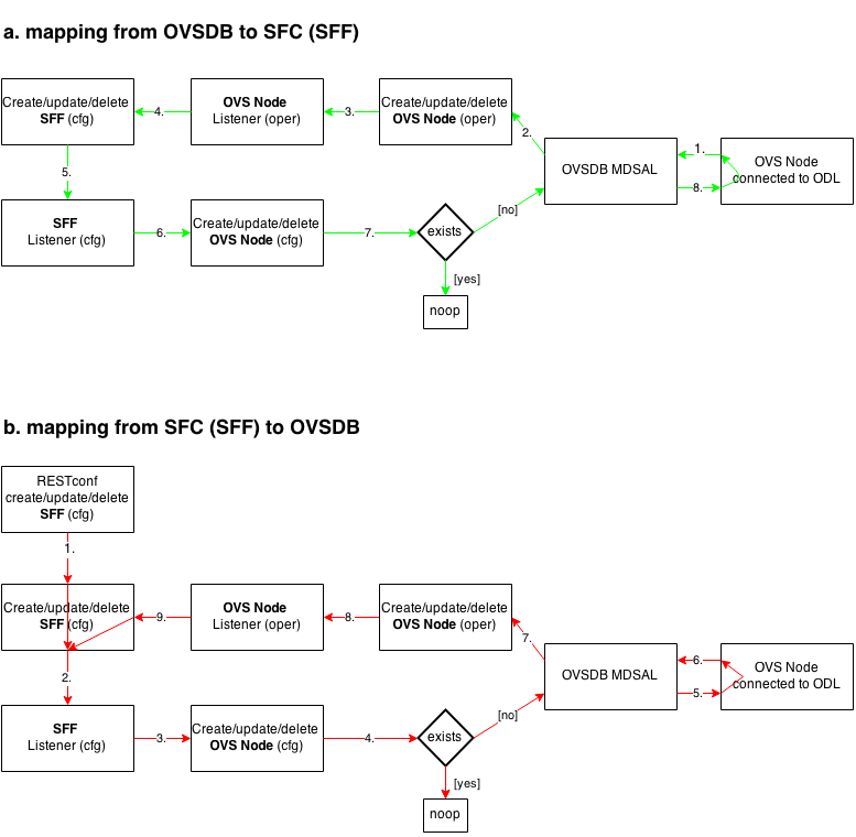
SFC < — > OVS mapping flow diagram
Key APIs and Interfaces
- SFF to OVS mapping API (methods to convert SFF object to OVS Bridge and OVS TerminationPoints)
- OVS to SFF mapping API (methods to convert OVS Bridge and OVS TerminationPoints to SFF object)
SFC Southbound REST Plug-in
Overview
The Southbound REST Plug-in is used to send configuration from datastore down to network devices supporting a REST API (i.e. they have a configured REST URI). It supports POST/PUT/DELETE operations, which are triggered accordingly by changes in the SFC data stores.
- Access Control List (ACL)
- Service Classifier Function (SCF)
- Service Function (SF)
- Service Function Group (SFG)
- Service Function Schedule Type (SFST)
- Service Function Forwarder (SFF)
- Rendered Service Path (RSP)
Southbound REST Plug-in Architecture
- listeners - used to listen on changes in the SFC data stores
- JSON exporters - used to export JSON-encoded data from binding-aware data store objects
- tasks - used to collect REST URIs of network devices and to send JSON-encoded data down to these devices
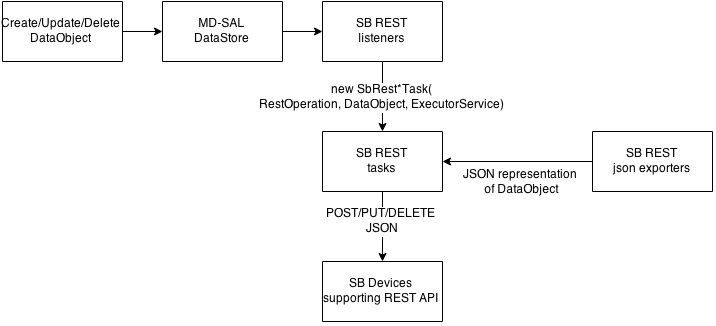
Southbound REST Plug-in Architecture diagram
Key APIs and Interfaces
The plug-in provides Southbound REST API designated to listening REST devices. It supports POST/PUT/DELETE operations. The operation (with corresponding JSON-encoded data) is sent to unique REST URL belonging to certain data type.
- Access Control List (ACL):
http://<host>:<port>/config/ietf-acl:access-lists/access-list/ - Service Function (SF):
http://<host>:<port>/config/service-function:service-functions/service-function/ - Service Function Group (SFG):
http://<host>:<port>/config/service-function:service-function-groups/service-function-group/ - Service Function Schedule Type (SFST):
http://<host>:<port>/config/service-function-scheduler-type:service-function-scheduler-types/service-function-scheduler-type/ - Service Function Forwarder (SFF):
http://<host>:<port>/config/service-function-forwarder:service-function-forwarders/service-function-forwarder/ - Rendered Service Path (RSP):
http://<host>:<port>/operational/rendered-service-path:rendered-service-paths/rendered-service-path/
Therefore, network devices willing to receive REST messages must listen on these REST URLs.
Note
Service Classifier Function (SCF) URL does not exist, because SCF is
considered as one of the network devices willing to receive REST
messages. However, there is a listener hooked on the SCF data store,
which is triggering POST/PUT/DELETE operations of ACL object,
because ACL is referenced in service-function-classifier.yang
Service Function Load Balancing Developer Guide
Overview
SFC Load-Balancing feature implements load balancing of Service Functions, rather than a one-to-one mapping between Service Function Forwarder and Service Function.
Load Balancing Architecture
Service Function Groups (SFG) can replace Service Functions (SF) in the Rendered Path model. A Service Path can only be defined using SFGs or SFs, but not a combination of both.
Relevant objects in the YANG model are as follows:
Service-Function-Group-Algorithm:
Service-Function-Group-Algorithms {
    Service-Function-Group-Algorithm {
        String name
        String type
    }
}
Available types: ALL, SELECT, INDIRECT, FAST_FAILURE
Service-Function-Group:
Service-Function-Groups {
    Service-Function-Group {
        String name
        String serviceFunctionGroupAlgorithmName
        String type
        String groupId
        Service-Function-Group-Element {
            String service-function-name
            int index
        }
    }
}
ServiceFunctionHop: holds a reference to a name of SFG (or SF)
Key APIs and Interfaces
This feature enhances the existing SFC API.
REST API commands include: * For Service Function Group (SFG): read existing SFG, write new SFG, delete existing SFG, add Service Function (SF) to SFG, and delete SF from SFG * For Service Function Group Algorithm (SFG-Alg): read, write, delete
Bundle providing the REST API: sfc-sb-rest * Service Function Groups and Algorithms are defined in: sfc-sfg and sfc-sfg-alg * Relevant JAVA API: SfcProviderServiceFunctionGroupAPI, SfcProviderServiceFunctionGroupAlgAPI
Service Function Scheduling Algorithms
Overview
When creating the Rendered Service Path (RSP), the earlier release of SFC chose the first available service function from a list of service function names. Now a new API is introduced to allow developers to develop their own schedule algorithms when creating the RSP. There are four scheduling algorithms (Random, Round Robin, Load Balance and Shortest Path) are provided as examples for the API definition. This guide gives a simple introduction of how to develop service function scheduling algorithms based on the current extensible framework.
Architecture
The following figure illustrates the service function selection framework and algorithms.
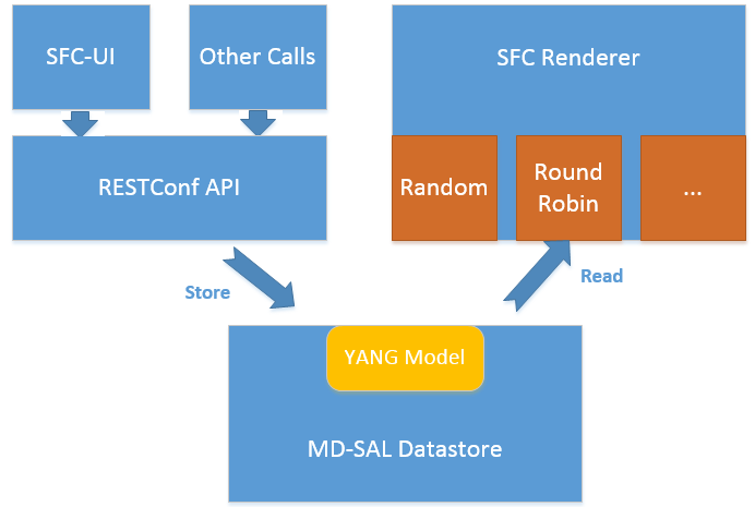
SF Scheduling Algorithm framework Architecture
The YANG Model defines the Service Function Scheduling Algorithm type identities and how they are stored in the MD-SAL data store for the scheduling algorithms.
The MD-SAL data store stores all informations for the scheduling algorithms, including their types, names, and status.
The API provides some basic APIs to manage the informations stored in the MD-SAL data store, like putting new items into it, getting all scheduling algorithms, etc.
The RESTCONF API provides APIs to manage the informations stored in the MD-SAL data store through RESTful calls.
The Service Function Chain Renderer gets the enabled scheduling algorithm type, and schedules the service functions with scheduling algorithm implementation.
Key APIs and Interfaces
While developing a new Service Function Scheduling Algorithm, a new class should be added and it should extend the base schedule class SfcServiceFunctionSchedulerAPI. And the new class should implement the abstract function:
public List<String> scheduleServiceFuntions(ServiceFunctionChain chain, int serviceIndex).
- ``ServiceFunctionChain chain``: the chain which will be rendered
- ``int serviceIndex``: the initial service index for this rendered service path
- ``List<String>``: a list of service function names which scheduled by the Service Function Scheduling Algorithm.
API Reference Documentation
Please refer the API docs generated in the mdsal-apidocs.
SFC Proof of Transit Developer Guide
Overview
SFC Proof of Transit implements the in-situ OAM (iOAM) Proof of Transit verification for SFCs and other paths. The implementation is broadly divided into the North-bound (NB) and the South-bound (SB) side of the application. The NB side is primarily charged with augmenting the RSP with user-inputs for enabling the PoT on the RSP, while the SB side is dedicated to auto-generated SFC PoT parameters, periodic refresh of these parameters and delivering the parameters to the NETCONF and iOAM capable nodes (eg. VPP instances).
Architecture
The following diagram gives the high level overview of the different parts.
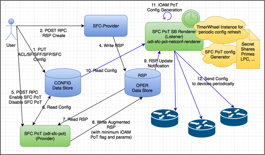
SFC Proof of Transit Internal Architecture
The Proof of Transit feature is enabled by two sub-features:
- ODL SFC PoT:
feature:install odl-sfc-pot - ODL SFC PoT NETCONF Renderer:
feature:install odl-sfc-pot-netconf-renderer
Details
The following classes and handlers are involved.
The class (SfcPotRpc) sets up RPC handlers for enabling the feature.
There are new RPC handlers for two new RPCs (EnableSfcIoamPotRenderedPath and DisableSfcIoamPotRenderedPath) and effected via SfcPotRspProcessor class.
When a user configures via a POST RPC call to enable Proof of Transit on a particular SFC (via the Rendered Service Path), the configuration drives the creation of necessary augmentations to the RSP (to modify the RSP) to effect the Proof of Transit configurations.
The augmentation meta-data added to the RSP are defined in the sfc-ioam-nb-pot.yang file.
Note
There are no auto generated configuration parameters added to the RSP to avoid RSP bloat.
Adding SFC Proof of Transit meta-data to the RSP is done in the SfcPotRspProcessor class.
Once the RSP is updated, the RSP data listeners in the SB renderer modules (odl-sfc-pot-netconf-renderer) will listen to the RSP changes and send out configurations to the necessary network nodes that are part of the SFC.
The configurations are handled mainly in the SfcPotAPI, SfcPotConfigGenerator, SfcPotPolyAPI, SfcPotPolyClass and SfcPotPolyClassAPI classes.
There is a sfc-ioam-sb-pot.yang file that shows the format of the iOAM PoT configuration data sent to each node of the SFC.
A timer is started based on the “ioam-pot-refresh-period” value in the SB renderer module that handles configuration refresh periodically.
The SB and timer handling are done in the odl-sfc-pot-netconf-renderer module. Note: This is NOT done in the NB odl-sfc-pot module to avoid periodic updates to the RSP itself.
ODL creates a new profile of a set of keys and secrets at a constant rate and updates an internal data store with the configuration. The controller labels the configurations per RSP as “even” or “odd” – and the controller cycles between “even” and “odd” labeled profiles. The rate at which these profiles are communicated to the nodes is configurable and in future, could be automatic based on profile usage. Once the profile has been successfully communicated to all nodes (all Netconf transactions completed), the controller sends an “enable pot-profile” request to the ingress node.
The nodes are to maintain two profiles (an even and an odd pot-profile). One profile is currently active and in use, and one profile is about to get used. A flag in the packet is indicating whether the odd or even pot-profile is to be used by a node. This is to ensure that during profile change we’re not disrupting the service. I.e. if the “odd” profile is active, the controller can communicate the “even” profile to all nodes and only if all the nodes have received it, the controller will tell the ingress node to switch to the “even” profile. Given that the indicator travels within the packet, all nodes will switch to the “even” profile. The “even” profile gets active on all nodes – and nodes are ready to receive a new “odd” profile.
HashedTimerWheel implementation is used to support the periodic configuration refresh. The default refresh is 5 seconds to start with.
Depending on the last updated profile, the odd or the even profile is updated in the fresh timer pop and the configurations are sent down appropriately.
SfcPotTimerQueue, SfcPotTimerWheel, SfcPotTimerTask, SfcPotTimerData and SfcPotTimerThread are the classes that handle the Proof of Transit protocol profile refresh implementation.
The RSP data store is NOT being changed periodically and the timer and configuration refresh modules are present in the SB renderer module handler and hence there are are no scale or RSP churn issues affecting the design.
The following diagram gives the overall sequence diagram of the interactions between the different classes.
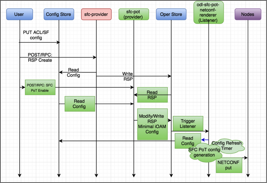
SFC Proof of Transit Sequence Diagram
Logical Service Function Forwarder
Overview
Rationale
When the current SFC is deployed in a cloud environment, it is assumed that each switch connected to a Service Function is configured as a Service Function Forwarder and each Service Function is connected to its Service Function Forwarder depending on the Compute Node where the Virtual Machine is located. This solution allows the basic cloud use cases to be fulfilled, as for example, the ones required in OPNFV Brahmaputra, however, some advanced use cases, like the transparent migration of VMs can not be implemented. The Logical Service Function Forwarder enables the following advanced use cases:
- Service Function mobility without service disruption
- Service Functions load balancing and failover
As shown in the picture below, the Logical Service Function Forwarder concept extends the current SFC northbound API to provide an abstraction of the underlying Data Center infrastructure. The Data Center underlaying network can be abstracted by a single SFF. This single SFF uses the logical port UUID as data plane locator to connect SFs globally and in a location-transparent manner. SFC makes use of Genius project to track the location of the SF’s logical ports.
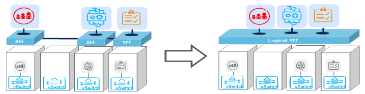
The SFC internally distributes the necessary flow state over the relevant switches based on the internal Data Center topology and the deployment of SFs.
Changes in data model
The Logical Service Function Forwarder concept extends the current SFC northbound API to provide an abstraction of the underlying Data Center infrastructure.
The Logical SFF simplifies the configuration of the current SFC data model by reducing the number of parameters to be be configured in every SFF, since the controller will discover those parameters by interacting with the services offered by the Genius project.
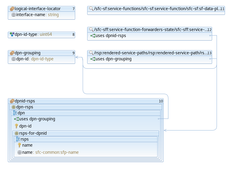
The following picture shows the Logical SFF data model. The model gets simplified as most of the configuration parameters of the current SFC data model are discovered in runtime. The complete YANG model can be found here logical SFF model.
There are other minor changes in the data model; the SFC encapsulation type has been added or moved in the following files:
Interaction with Genius
Feature sfc-genius functionally enables SFC integration with Genius. This allows configuring a Logical SFF and SFs attached to this Logical SFF via logical interfaces (i.e. neutron ports) that are registered with Genius.
As shown in the following picture, SFC will interact with Genius project’s services to provide the Logical SFF functionality.
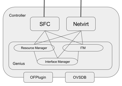
The following are the main Genius’ services used by SFC:
- Interaction with Interface Tunnel Manager (ITM)
- Interaction with the Interface Manager
- Interaction with Resource Manager
SFC Service registration with Genius
Genius handles the coexistence of different network services. As such, SFC service is registered with Genius performing the following actions:
- SFC Service Binding
- As soon as a Service Function associated to the Logical SFF is involved in a Rendered Service Path, SFC service is bound to its logical interface via Genius Interface Manager. This has the effect of forwarding every incoming packet from the Service Function to the SFC pipeline of the attached switch, as long as it is not consumed by a different bound service with higher priority.
- SFC Service Terminating Action
- As soon as SFC service is bound to the interface of a Service Function for the first time on a specific switch, a terminating service action is configured on that switch via Genius Interface Tunnel Manager. This has the effect of forwarding every incoming packet from a different switch to the SFC pipeline as long as the traffic is VXLAN encapsulated on VNI 0.
The following sequence diagrams depict how the overall process takes place:
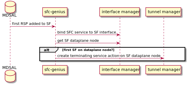
SFC genius module interaction with Genius at RSP creation.
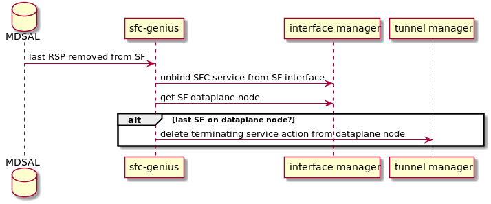
SFC genius module interaction with Genius at RSP removal.
For more information on how Genius allows different services to coexist, see the Genius User Guide.
Path Rendering
During path rendering, Genius is queried to obtain needed information, such as:
- Location of a logical interface on the data-plane.
- Tunnel interface for a specific pair of source and destination switches.
- Egress OpenFlow actions to output packets to a specific interface.
See RSP Rendering section for more information.
VM migration
Upon VM migration, it’s logical interface is first unregistered and then registered with Genius, possibly at a new physical location. sfc-genius reacts to this by re-rendering all the RSPs on which the associated SF participates, if any.
The following picture illustrates the process:
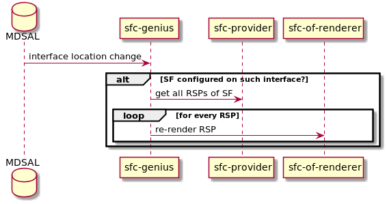
SFC genius module at VM migration.
RSP Rendering changes for paths using the Logical SFF
Construction of the auxiliary rendering graph
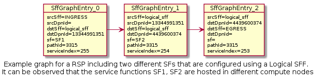
When starting the rendering of a RSP, the SFC renderer builds an auxiliary graph with information about the required hops for traffic traversing the path. RSP processing is achieved by iteratively evaluating each of the entries in the graph, writing the required flows in the proper switch for each hop.
It is important to note that the graph includes both traffic ingress (i.e. traffic entering into the first SF) and traffic egress (i.e. traffic leaving the chain from the last SF) as hops. Therefore, the number of entries in the graph equals the number of SFs in the chain plus one.
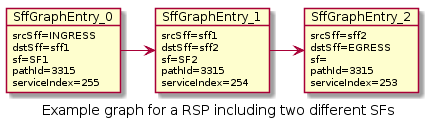
The process of rendering a chain when the switches involved are part of the Logical SFF also starts with the construction of the hop graph. The difference is that when the SFs used in the chain are using a logical interface, the SFC renderer will also retrieve from Genius the DPIDs for the switches, storing them in the graph. In this context, those switches are the ones in the compute nodes each SF is hosted on at the time the chain is rendered.
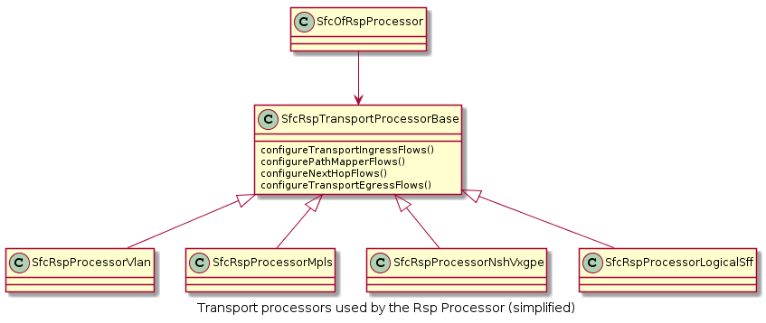
New transport processor
Transport processors are classes which calculate and write the correct flows for a chain. Each transport processor specializes on writing the flows for a given combination of transport type and SFC encapsulation.
A specific transport processor has been created for paths using a Logical SFF. A particularity of this transport processor is that its use is not only determined by the transport / SFC encapsulation combination, but also because the chain is using a Logical SFF. The actual condition evaluated for selecting the Logical SFF transport processor is that the SFs in the chain are using logical interface locators, and that the DPIDs for those locators can be successfully retrieved from Genius.
The main differences between the Logical SFF transport processor and other processors are the following:
- Instead of srcSff, dstSff fields in the hops graph (which are all equal in a path using a Logical SFF), the Logical SFF transport processor uses previously stored srcDpnId, dstDpnId fields in order to know whether an actual hop between compute nodes must be performed or not (it is possible that two consecutive SFs are collocated in the same compute node).
- When a hop between switches really has to be performed, it relies on Genius for getting the actions to perform that hop. The retrieval of those actions involve two steps:
- First, Genius’ Overlay Tunnel Manager module is used in order to retrieve the target interface for a jump between the source and the destination DPIDs.
- Then, egress instructions for that interface are retrieved from Genius’s Interface Manager.
- There are no next hop rules between compute nodes, only egress instructions (the transport zone tunnels have all the required routing information).
- Next hop information towards SFs uses mac adresses which are also retrieved from the Genius datastore.
- The Logical SFF transport processor performs NSH decapsulation in the last switch of the chain.
Post-rendering update of the operational data model
When the rendering of a chain finishes successfully, the Logical SFF Transport Processor perform two operational datastore modifications in order to provide some relevant runtime information about the chain. The exposed information is the following:
- Rendered Service Path state: when the chain uses a Logical SFF, DPIDs for the switches in the compute nodes on which the SFs participating in the chain are hosted are added to the hop information.
- SFF state: A new list of all RSPs which use each DPID is has been added. It is updated on each RSP addition / deletion.
Classifier impacts
This section explains the changes made to the SFC classifier, enabling it to be attached to Logical SFFs.
Refer to the following image to better understand the concept, and the required steps to implement the feature.
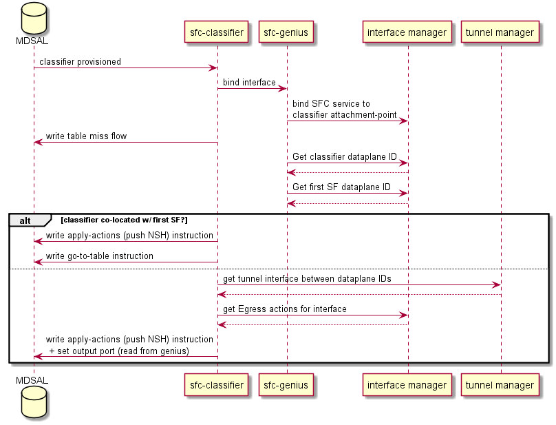
SFC classifier integration with Genius.
As stated in the SFC User Guide, the classifier needs to be provisioned using logical interfaces as attachment points.
When that happens, MDSAL will trigger an event in the odl-sfc-scf-openflow feature (i.e. the sfc-classifier), which is responsible for installing the classifier flows in the classifier switches.
The first step of the process, is to bind the interfaces to classify in Genius, in order for the desired traffic (originating from the VMs having the provisioned attachment-points) to enter the SFC pipeline. This will make traffic reach table 82 (SFC classifier table), coming from table 0 (table managed by Genius, shared by all applications).
The next step, is deciding which flows to install in the SFC classifier table. A table-miss flow will be installed, having a MatchAny clause, whose action is to jump to Genius’s egress dispatcher table. This enables traffic intended for other applications to still be processed.
The flow that allows the SFC pipeline to continue is added next, having higher match priority than the table-miss flow. This flow has two responsabilities:
Push the NSH header, along with its metadata (required within the SFC pipeline)
Features the specified ACL matches as match criteria, and push NSH along with its metadata into the Action list.
Advance the SFC pipeline
Forward the traffic to the first Service Function in the RSP. This steers packets into the SFC domain, and how it is done depends on whether the classifier is co-located with the first service function in the specified RSP.
Should the classifier be co-located (i.e. in the same compute node), a new instruction is appended to the flow, telling all matches to jump to the transport ingress table.
If not, Genius’s tunnel manager service is queried to get the tunnel interface connecting the classifier node with the compute node where the first Service Function is located, and finally, Genius’s interface manager service is queried asking for instructions on how to reach that tunnel interface.
These actions are then appended to the Action list already containing push NSH and push NSH metadata Actions, and written in an Apply-Actions Instruction into the datastore.