Controller
Overview
OpenDaylight Controller is Java-based, model-driven controller using YANG as its modeling language for various aspects of the system and applications and with its components serves as a base platform for other OpenDaylight applications.
The OpenDaylight Controller relies on the following technologies:
OSGI - This framework is the back-end of OpenDaylight as it allows dynamically loading of bundles and packages JAR files, and binding bundles together for exchanging information.
Karaf - Application container built on top of OSGI, which simplifies operational aspects of packaging and installing applications.
YANG - a data modeling language used to model configuration and state data manipulated by the applications, remote procedure calls, and notifications.
The OpenDaylight Controller provides following model-driven subsystems as a foundation for Java applications:
Config Subsystem - an activation, dependency-injection and configuration framework, which allows two-phase commits of configuration and dependency-injection, and allows for run-time rewiring.
MD-SAL - messaging and data storage functionality for data, notifications and RPCs modeled by application developers. MD-SAL uses YANG as the modeling for both interface and data definitions, and provides a messaging and data-centric runtime for such services based on YANG modeling.
MD-SAL Clustering - enables cluster support for core MD-SAL functionality and provides location-transparent accesss to YANG-modeled data.
The OpenDaylight Controller supports external access to applications and data using following model-driven protocols:
NETCONF - XML-based RPC protocol, which provides abilities for client to invoke YANG-modeled RPCs, receive notifications and to read, modify and manipulate YANG modeled data.
RESTCONF - HTTP-based protocol, which provides REST-like APIs to manipulate YANG modeled data and invoke YANG modeled RPCs, using XML or JSON as payload format.
MD-SAL Overview
The Model-Driven Service Adaptation Layer (MD-SAL) is message-bus inspired extensible middleware component that provides messaging and data storage functionality based on data and interface models defined by application developers (i.e. user-defined models).
The MD-SAL:
Defines a common-layer, concepts, data model building blocks and messaging patterns and provides infrastructure / framework for applications and inter-application communication.
Provide common support for user-defined transport and payload formats, including payload serialization and adaptation (e.g. binary, XML or JSON).
The MD-SAL uses YANG as the modeling language for both interface and data definitions, and provides a messaging and data-centric runtime for such services based on YANG modeling.
MD-SAL Binding: MD-SAL APIs which extensively uses APIs and classes generated from YANG models, which provides compile-time safety.
MD-SAL DOM: (Document Object Model) APIs which uses DOM-like representation of data, which makes them more powerful, but provides less compile-time safety.
Note
Model-driven nature of the MD-SAL and DOM-based APIs allows for behind-the-scene API and payload type mediation and transformation to facilitate seamless communication between applications - this enables for other components and applications to provide connectors / expose different set of APIs and derive most of its functionality purely from models, which all existing code can benefit from without modification. For example RESTCONF Connector is an application built on top of MD-SAL and exposes YANG-modeled application APIs transparently via HTTP and adds support for XML and JSON payload type.
Basic concepts
Basic concepts are building blocks which are used by applications, and from which MD-SAL uses to define messaging patterns and to provide services and behavior based on developer-supplied YANG models.
- Data Tree
All state-related data are modeled and represented as data tree, with possibility to address any element / subtree
Operational Data Tree - Reported state of the system, published by the providers using MD-SAL. Represents a feedback loop for applications to observe state of the network / system.
Configuration Data Tree - Intended state of the system or network, populated by consumers, which expresses their intention.
- Instance Identifier
Unique identifier of node / subtree in data tree, which provides unambiguous information, how to reference and retrieve node / subtree from conceptual data trees.
- Notification
Asynchronous transient event which may be consumed by subscribers and they may act upon it
- RPC
asynchronous request-reply message pair, when request is triggered by consumer, send to the provider, which in future replies with reply message.
Note
In MD-SAL terminology, the term RPC is used to define the input and output for a procedure (function) that is to be provided by a provider, and mediated by the MD-SAL, that means it may not result in remote call.
Messaging Patterns
MD-SAL provides several messaging patterns using broker derived from basic concepts, which are intended to transfer YANG modeled data between applications to provide data-centric integration between applications instead of API-centric integration.
Unicast communication
Remote Procedure Calls - unicast between consumer and provider, where consumer sends request message to provider, which asynchronously responds with reply message
Publish / Subscribe
Notifications - multicast transient message which is published by provider and is delivered to subscribers
Data Change Events - multicast asynchronous event, which is sent by data broker if there is change in conceptual data tree, and is delivered to subscribers
Transactional access to Data Tree
Transactional reads from conceptual data tree - read-only transactions with isolation from other running transactions.
Transactional modification to conceptual data tree - write transactions with isolation from other running transactions.
Transaction chaining
MD-SAL Data Transactions
MD-SAL Data Broker provides transactional access to conceptual data trees representing configuration and operational state.
Note
Data tree usually represents state of the modeled data, usually this is state of controller, applications and also external systems (network devices).
Transactions provide stable and isolated view from other currently running transactions. The state of running transaction and underlying data tree is not affected by other concurrently running transactions.
- Write-Only
Transaction provides only modification capabilities, but does not provide read capabilities. Write-only transaction is allocated using
newWriteOnlyTransaction().Note
This allows less state tracking for write-only transactions and allows MD-SAL Clustering to optimize internal representation of transaction in cluster.
- Read-Write
Transaction provides both read and write capabilities. It is allocated using
newReadWriteTransaction().- Read-Only
Transaction provides stable read-only view based on current data tree. Read-only view is not affected by any subsequent write transactions. Read-only transaction is allocated using
newReadOnlyTransaction().Note
If an application needs to observe changes itself in data tree, it should use data tree listeners instead of read-only transactions and polling data tree.
Transactions may be allocated using the data broker itself or using transaction chain. In the case of transaction chain, the new allocated transaction is not based on current state of data tree, but rather on state introduced by previous transaction from the same chain, even if the commit for previous transaction has not yet occurred (but transaction was submitted).
Write-Only & Read-Write Transaction
Write-Only and Read-Write transactions provide modification capabilities for the conceptual data trees.
application allocates new transactions using
newWriteOnlyTransaction()ornewReadWriteTransaction().application modifies data tree using
put,mergeand/ordelete.application finishes transaction using
submit(), which seals transaction and submits it to be processed.application observes the result of the transaction commit using either blocking or asynchronous calls.
The initial state of the write transaction is a stable snapshot of the current data tree state captured when transaction was created and it’s state and underlying data tree are not affected by other concurrently running transactions.
Write transactions are isolated from other concurrent write transactions. All writes are local to the transaction and represents only a proposal of state change for data tree and are not visible to any other concurrently running transactions (including read-only transactions).
The transaction commit may fail due to failing verification of data or concurrent transaction modifying and affected data in an incompatible way.
Modification of Data Tree
Write-only and read-write transaction provides following methods to modify data tree:
- put
<T> void put(LogicalDatastoreType store, InstanceIdentifier<T> path, T data);
Stores a piece of data at a specified path. This acts as an add / replace operation, which is to say that whole subtree will be replaced by the specified data.
- merge
<T> void merge(LogicalDatastoreType store, InstanceIdentifier<T> path, T data);
Merges a piece of data with the existing data at a specified path. Any pre-existing data which are not explicitly overwritten will be preserved. This means that if you store a container, its child subtrees will be merged.
- delete
void delete(LogicalDatastoreType store, InstanceIdentifier<?> path);
Removes a whole subtree from a specified path.
Submitting transaction
Transaction is submitted to be processed and committed using following method:
CheckedFuture<Void,TransactionCommitFailedException> submit();
Applications publish the changes proposed in the transaction by calling
submit() on the transaction. This seals the transaction
(preventing any further writes using this transaction) and submits it to
be processed and applied to global conceptual data tree. The
submit() method does not block, but rather returns
ListenableFuture, which will complete successfully once processing
of transaction is finished and changes are applied to data tree. If
commit of data failed, the future will fail with
TransactionFailedException.
Application may listen on commit state asynchronously using
ListenableFuture.
Futures.addCallback( writeTx.submit(), new FutureCallback<Void>() {
        public void onSuccess( Void result ) {
            LOG.debug("Transaction committed successfully.");
        }

        public void onFailure( Throwable t ) {
            LOG.error("Commit failed.",e);
        }
    });
Submits
writeTxand registers application providedFutureCallbackon returned future.Invoked when future completed successfully - transaction
writeTxwas successfully committed to data tree.Invoked when future failed - commit of transaction
writeTxfailed. Supplied exception provides additional details and cause of failure.
If application need to block till commit is finished it may use
checkedGet() to wait till commit is finished.
try {
    writeTx.submit().checkedGet();
} catch (TransactionCommitFailedException e) {
    LOG.error("Commit failed.",e);
}
Submits
writeTxand blocks till commit ofwriteTxis finished. If commit failsTransactionCommitFailedExceptionwill be thrown.Catches
TransactionCommitFailedExceptionand logs it.
Transaction local state
Read-Write transactions maintain transaction-local state, which renders all modifications as if they happened, but this is only local to transaction.
Reads from the transaction returns data as if the previous modifications in transaction already happened.
Let assume initial state of data tree for PATH is A.
ReadWriteTransaction rwTx = broker.newReadWriteTransaction();

rwRx.read(OPERATIONAL,PATH).get();
rwRx.put(OPERATIONAL,PATH,B);
rwRx.read(OPERATIONAL,PATH).get();
rwRx.put(OPERATIONAL,PATH,C);
rwRx.read(OPERATIONAL,PATH).get();
Allocates new
ReadWriteTransaction.Read from
rwTxwill return valueAforPATH.Writes value
BtoPATHusingrwTx.Read will return value
BforPATH, since previous write occurred in same transaction.Writes value
CtoPATHusingrwTx.Read will return value
CforPATH, since previous write occurred in same transaction.
Transaction isolation
Running (not submitted) transactions are isolated from each other and changes done in one transaction are not observable in other currently running transaction.
Lets assume initial state of data tree for PATH is A.
ReadOnlyTransaction txRead = broker.newReadOnlyTransaction();
ReadWriteTransaction txWrite = broker.newReadWriteTransaction();

txRead.read(OPERATIONAL,PATH).get();
txWrite.put(OPERATIONAL,PATH,B);
txWrite.read(OPERATIONAL,PATH).get();
txWrite.submit().get();
txRead.read(OPERATIONAL,PATH).get();
txAfterCommit = broker.newReadOnlyTransaction();
txAfterCommit.read(OPERATIONAL,PATH).get();
Allocates read only transaction, which is based on data tree which contains value
AforPATH.Allocates read write transaction, which is based on data tree which contains value
AforPATH.Read from read-only transaction returns value
AforPATH.Data tree is updated using read-write transaction,
PATHcontainsB. Change is not public and only local to transaction.Read from read-write transaction returns value
BforPATH.Submits changes in read-write transaction to be committed to data tree. Once commit will finish, changes will be published and
PATHwill be updated for valueB. Previously allocated transactions are not affected by this change.Read from previously allocated read-only transaction still returns value
AforPATH, since it provides stable and isolated view.Allocates new read-only transaction, which is based on data tree, which contains value
BforPATH.Read from new read-only transaction return value
BforPATHsince read-write transaction was committed.
Note
Examples contain blocking calls on future only to illustrate that
action happened after other asynchronous action. The use of the
blocking call ListenableFuture#get() is discouraged for most
use-cases and you should use
Futures#addCallback(ListenableFuture, FutureCallback) to listen
asynchronously for result.
Commit failure scenarios
A transaction commit may fail because of following reasons:
- Optimistic Lock Failure
Another transaction finished earlier and modified the same node in a non-compatible way. The commit (and the returned future) will fail with an
OptimisticLockFailedException.It is the responsibility of the caller to create a new transaction and submit the same modification again in order to update data tree.
Warning
OptimisticLockFailedExceptionusually exposes multiple writers to the same data subtree, which may conflict on same resources.In most cases, retrying may result in a probability of success.
There are scenarios, albeit unusual, where any number of retries will not succeed. Therefore it is strongly recommended to limit the number of retries (2 or 3) to avoid an endless loop.
- Data Validation
The data change introduced by this transaction did not pass validation by commit handlers or data was incorrectly structured. The returned future will fail with a
DataValidationFailedException. User should not retry to create new transaction with same data, since it probably will fail again.
Example conflict of two transactions
This example illustrates two concurrent transactions, which derived from same initial state of data tree and proposes conflicting modifications.
WriteTransaction txA = broker.newWriteTransaction();
WriteTransaction txB = broker.newWriteTransaction();

txA.put(CONFIGURATION, PATH, A);
txB.put(CONFIGURATION, PATH, B);

CheckedFuture<?,?> futureA = txA.submit();
CheckedFuture<?,?> futureB = txB.submit();
Updates
PATHto valueAusingtxAUpdates
PATHto valueBusingtxBSeals & submits
txA. The commit will be processed asynchronously and data tree will be updated to contain valueAforPATH. The returned ‘ListenableFuture’ will complete successfully once state is applied to data tree.Seals & submits
txB. Commit oftxBwill fail, because previous transaction also modified path in a concurrent way. The state introduced bytxBwill not be applied. The returnedListenableFuturewill fail withOptimisticLockFailedExceptionexception, which indicates that concurrent transaction prevented the submitted transaction from being applied.
Example asynchronous retry-loop
private void doWrite( final int tries ) {
    WriteTransaction writeTx = dataBroker.newWriteOnlyTransaction();

    MyDataObject data = ...;
    InstanceIdentifier<MyDataObject> path = ...;
    writeTx.put( LogicalDatastoreType.OPERATIONAL, path, data );

    Futures.addCallback( writeTx.submit(), new FutureCallback<Void>() {
        public void onSuccess( Void result ) {
            // succeeded
        }

        public void onFailure( Throwable t ) {
            if( t instanceof OptimisticLockFailedException && (( tries - 1 ) > 0)) {
                doWrite( tries - 1 );
            }
        }
      });
}
...
doWrite( 2 );
Concurrent change compatibility
There are several sets of changes which could be considered incompatible between two transactions which are derived from same initial state. Rules for conflict detection applies recursively for each subtree level.
Following table shows state changes and failures between two concurrent
transactions, which are based on same initial state, tx1 is
submitted before tx2.
INFO: Following tables stores numeric values and shows data using
toString() to simplify examples.
Initial state |
tx1 |
tx2 |
Observable Result |
|---|---|---|---|
Empty |
|
|
|
Empty |
|
|
value of |
Empty |
|
|
|
Empty |
|
|
|
A=0 |
|
|
|
A=0 |
|
|
|
A=0 |
|
|
|
A=0 |
|
|
|
A=0 |
|
|
|
A=0 |
|
|
|
Table: Concurrent change resolution for leaves and leaf-list items
Initial state |
|
|
Result |
|---|---|---|---|
Empty |
put(TOP,[]) |
put(TOP,[]) |
|
Empty |
put(TOP,[]) |
merge(TOP,[]) |
TOP=[] |
Empty |
put(TOP,[FOO=1]) |
put(TOP,[BAR=1]) |
|
Empty |
put(TOP,[FOO=1]) |
merge(TOP,[BAR=1]) |
TOP=[FOO=1,BAR=1] |
Empty |
merge(TOP,[FOO=1]) |
put(TOP,[BAR=1]) |
|
Empty |
merge(TOP,[FOO=1]) |
merge(TOP,[BAR=1]) |
TOP=[FOO=1,BAR=1] |
TOP=[] |
put(TOP,[FOO=1]) |
put(TOP,[BAR=1]) |
|
TOP=[] |
put(TOP,[FOO=1]) |
merge(TOP,[BAR=1]) |
state is TOP=[FOO=1,BAR=1] |
TOP=[] |
merge(TOP,[FOO=1]) |
put(TOP,[BAR=1]) |
|
TOP=[] |
merge(TOP,[FOO=1]) |
merge(TOP,[BAR=1]) |
state is TOP=[FOO=1,BAR=1] |
TOP=[] |
delete(TOP) |
put(TOP,[BAR=1]) |
|
TOP=[] |
delete(TOP) |
merge(TOP,[BAR=1]) |
state is TOP=[BAR=1] |
TOP=[] |
put(TOP/FOO,1) |
put(TOP/BAR,1]) |
state is TOP=[FOO=1,BAR=1] |
TOP=[] |
put(TOP/FOO,1) |
merge(TOP/BAR,1) |
state is TOP=[FOO=1,BAR=1] |
TOP=[] |
merge(TOP/FOO,1) |
put(TOP/BAR,1) |
state is TOP=[FOO=1,BAR=1] |
TOP=[] |
merge(TOP/FOO,1) |
merge(TOP/BAR,1) |
state is TOP=[FOO=1,BAR=1] |
TOP=[] |
delete(TOP) |
put(TOP/BAR,1) |
|
TOP=[] |
delete(TOP) |
merge(TOP/BAR,1] |
|
TOP=[FOO=1] |
put(TOP/FOO,2) |
put(TOP/BAR,1) |
state is TOP=[FOO=2,BAR=1] |
TOP=[FOO=1] |
put(TOP/FOO,2) |
merge(TOP/BAR,1) |
state is TOP=[FOO=2,BAR=1] |
TOP=[FOO=1] |
merge(TOP/FOO,2) |
put(TOP/BAR,1) |
state is TOP=[FOO=2,BAR=1] |
TOP=[FOO=1] |
merge(TOP/FOO,2) |
merge(TOP/BAR,1) |
state is TOP=[FOO=2,BAR=1] |
TOP=[FOO=1] |
delete(TOP/FOO) |
put(TOP/BAR,1) |
state is TOP=[BAR=1] |
TOP=[FOO=1] |
delete(TOP/FOO) |
merge(TOP/BAR,1] |
state is TOP=[BAR=1] |
Table: Concurrent change resolution for containers, lists, list items
MD-SAL RPC routing
The MD-SAL provides a way to deliver Remote Procedure Calls (RPCs) to a particular implementation based on content in the input as it is modeled in YANG. This part of the RPC input is referred to as a context reference.
The MD-SAL does not dictate the name of the leaf which is used for this RPC routing, but provides necessary functionality for YANG model author to define their context reference in their model of RPCs.
MD-SAL routing behavior is modeled using following terminology and its application to YANG models:
- Context Type
Logical type of RPC routing. Context type is modeled as YANG
identityand is referenced in model to provide scoping information.- Context Instance
Conceptual location in data tree, which represents context in which RPC could be executed. Context instance usually represent logical point to which RPC execution is attached.
- Context Reference
Field of RPC input payload which contains Instance Identifier referencing context instance in which the RPC should be executed.
Modeling a routed RPC
In order to define routed RPCs, the YANG model author needs to declare (or reuse) a context type, set of possible context instances and finally RPCs which will contain context reference on which they will be routed.
Declaring a routing context type
identity node-context {
    description "Identity used to mark node context";
}
This declares an identity named node-context, which is used as
marker for node-based routing and is used in other places to reference
that routing type.
Declaring possible context instances
In order to define possible values of context instances for routed
RPCs, we need to model that set accordingly using context-instance
extension from the yang-ext model.
import yang-ext { prefix ext; }

/** Base structure **/
container nodes {
    list node {
        key "id";
        ext:context-instance "node-context";
        // other node-related fields would go here
    }
}
The statement ext:context-instance "node-context"; marks any element
of the list node as a possible valid context instance in
node-context based routing.
Note
The existence of a context instance node in operational or config data tree is not strongly tied to existence of RPC implementation.
For most routed RPC models, there is relationship between the data present in operational data tree and RPC implementation availability, but this is not enforced by MD-SAL. This provides some flexibility for YANG model writers to better specify their routing model and requirements for implementations. Details when RPC implementations are available should be documented in YANG model.
If user invokes RPC with a context instance that has no
registered implementation, the RPC invocation will fail with the
exception DOMRpcImplementationNotAvailableException.
Declaring a routed RPC
To declare RPC to be routed based on node-context we need to add
leaf of instance-identifier type (or type derived from
instance-identifier) to the RPC and mark it as context
reference.
This is achieved using YANG extension context-reference from
yang-ext model on leaf, which will be used for RPC routing.
rpc example-routed-rpc  {
    input {
        leaf node {
            ext:context-reference "node-context";
            type "instance-identifier";
        }
        // other input to the RPC would go here
    }
}
The statement ext:context-reference "node-context" marks
leaf node as context reference of type node-context. The
value of this leaf, will be used by the MD-SAL to select the particular
RPC implementation that registered itself as the implementation of the
RPC for particular context instance.
Using routed RPCs
From a user perspective (e.g. invoking RPCs) there is no difference between routed and non-routed RPCs. Routing information is just an additional leaf in RPC which must be populated.
Implementing a routed RPC
Implementation
Registering implementations
Implementations of a routed RPC (e.g., southbound plugins) will specify an instance-identifier for the context reference (in this case a node) for which they want to provide an implementation during registration. Consumers, e.g., those calling the RPC are required to specify that instance-identifier (in this case the identifier of a node) when invoking RPC.
Simple code which showcases that for add-flow via Binding-Aware APIs (RoutedServiceTest.java ):
61  @Override
62  public void onSessionInitiated(ProviderContext session) {
63      assertNotNull(session);
64      firstReg = session.addRoutedRpcImplementation(SalFlowService.class, salFlowService1);
65  }
Line 64: We are registering salFlowService1 as implementation of SalFlowService RPC
107  NodeRef nodeOne = createNodeRef("foo:node:1");
109  /**
110   * Provider 1 registers path of node 1
111   */
112  firstReg.registerPath(NodeContext.class, nodeOne);
Line 107: We are creating NodeRef (encapsulation of InstanceIdentifier) for “foo:node:1”.
Line 112: We register salFlowService1 as implementation for nodeOne.
The salFlowService1 will be executed only for RPCs which contains Instance Identifier for foo:node:1.
RPCs and cluster
In case there is is only a single provider of an RPC in the cluster the RPC registration is propagated to other nodes via Gossip protocol and the RPC calls from other nodes are correctly routed to the provider. Since the registrations are not expected to change rapidly there is a latency of about 1 second until the registration is reflected on the remote nodes.
OpenDaylight Controller MD-SAL: RESTCONF
RESTCONF operations overview
Config: Contains data inserted via controller
Operational: Contains other data
Note
RESTCONF supports OPTIONS, GET, PUT, POST, and
DELETE operations. Request and response data can either be in the
XML or JSON format. XML structures according to yang are defined at:
XML-YANG. JSON structures are
defined at:
JSON-YANG.
Data in the request must have a correctly set Content-Type field in
the http header with the allowed value of the media type. The media type
of the requested data has to be set in the Accept field. Get the
media types for each resource by calling the OPTIONS operation. Most of
the paths of the pathsRestconf endpoints use Instance
Identifier.
<identifier> is used in the explanation of the operations.
It must start with <moduleName>:<nodeName> where <moduleName> is a name of the module and <nodeName> is the name of a node in the module. It is sufficient to just use <nodeName> after <moduleName>:<nodeName>. Each <nodeName> has to be separated by /.
<nodeName> can represent a data node which is a list or container yang built-in type. If the data node is a list, there must be defined keys of the list behind the data node name for example, <nodeName>/<valueOfKey1>/<valueOfKey2>.
- The format <moduleName>:<nodeName> has to be used in this case as well:Module A has node A1. Module B augments node A1 by adding node X. Module C augments node A1 by adding node X. For clarity, it has to be known which node is X (for example: C:X). For more details about encoding, see: RESTCONF 02 - Encoding YANG Instance Identifiers in the Request URI.
Mount point
HTTP methods
OPTIONS /restconf
Returns the XML description of the resources with the required request and response media types in Web Application Description Language (WADL)
GET /restconf/config/<identifier>
Returns a data node from the Config datastore.
<identifier> points to a data node which must be retrieved.
GET /restconf/operational/<identifier>
Returns the value of the data node from the Operational datastore.
<identifier> points to a data node which must be retrieved.
PUT /restconf/config/<identifier>
Updates or creates data in the Config datastore and returns the state about success.
<identifier> points to a data node which must be stored.
PUT http://<controllerIP>:8080/restconf/config/module1:foo/bar
Content-Type: applicaton/xml
<bar>
  …
</bar>
PUT http://<controllerIP>:8080/restconf/config/module1:foo1/foo2/yang-ext:mount/module2:foo/bar
Content-Type: applicaton/xml
<bar>
  …
</bar>
POST /restconf/config
Creates the data if it does not exist
POST URL: http://localhost:8080/restconf/config/
content-type: application/yang.data+json
JSON payload:

   {
     "toaster:toaster" :
     {
       "toaster:toasterManufacturer" : "General Electric",
       "toaster:toasterModelNumber" : "123",
       "toaster:toasterStatus" : "up"
     }
  }
POST /restconf/config/<identifier>
Creates the data if it does not exist in the Config datastore, and returns the state about success.
<identifier> points to a data node where data must be stored.
The root element of data must have the namespace (data are in XML) or module name (data are in JSON.)
POST http://<controllerIP>:8080/restconf/config/module1:foo
Content-Type: applicaton/xml/
<bar xmlns=“module1namespace”>
  …
</bar>
Example with mount point:
http://<controllerIP>:8080/restconf/config/module1:foo1/foo2/yang-ext:mount/module2:foo
Content-Type: applicaton/xml
<bar xmlns=“module2namespace”>
  …
</bar>
POST /restconf/operations/<moduleName>:<rpcName>
Invokes RPC.
<moduleName>:<rpcName> - <moduleName> is the name of the module and <rpcName> is the name of the RPC in this module.
The Root element of the data sent to RPC must have the name “input”.
The result can be the status code or the retrieved data having the root element “output”.
POST http://<controllerIP>:8080/restconf/operations/module1:fooRpc
Content-Type: applicaton/xml
Accept: applicaton/xml
<input>
  …
</input>

The answer from the server could be:
<output>
  …
</output>
POST http://localhost:8080/restconf/operations/toaster:make-toast
Content-Type: application/yang.data+json
{
  "input" :
  {
     "toaster:toasterDoneness" : "10",
     "toaster:toasterToastType":"wheat-bread"
  }
}
Note
Even though this is a default for the toasterToastType value in the yang, you still need to define it.
DELETE /restconf/config/<identifier>
Removes the data node in the Config datastore and returns the state about success.
<identifier> points to a data node which must be removed.
More information is available in the RESTCONF RFC.
How RESTCONF works
- InstanceIdentifier
Represents the path in the data tree
- ConsumerSession
Used for invoking RPCs
- DataBrokerService
Offers manipulation with transactions and reading data from the datastores
- SchemaContext
Holds information about yang modules
- MountService
Returns MountInstance based on the InstanceIdentifier pointing to a mount point
- MountInstace
Contains the SchemaContext behind the mount point
- DataSchemaNode
Provides information about the schema node
- SimpleNode
Possesses the same name as the schema node, and contains the value representing the data node value
- CompositeNode
Can contain CompositeNode-s and SimpleNode-s
GET in action
Figure 1 shows the GET operation with URI restconf/config/M:N where M is the module name, and N is the node name.
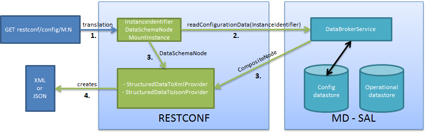
Get
The requested URI is translated into the InstanceIdentifier which points to the data node. During this translation, the DataSchemaNode that conforms to the data node is obtained. If the data node is behind the mount point, the MountInstance is obtained as well.
RESTCONF asks for the value of the data node from DataBrokerService based on InstanceIdentifier.
DataBrokerService returns CompositeNode as data.
StructuredDataToXmlProvider or StructuredDataToJsonProvider is called based on the Accept field from the http request. These two providers can transform CompositeNode regarding DataSchemaNode to an XML or JSON document.
XML or JSON is returned as the answer on the request from the client.
PUT in action
Figure 2 shows the PUT operation with the URI restconf/config/M:N where M is the module name, and N is the node name. Data is sent in the request either in the XML or JSON format.
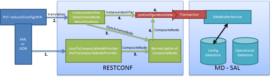
Put
Input data is sent to JsonToCompositeNodeProvider or XmlToCompositeNodeProvider. The correct provider is selected based on the Content-Type field from the http request. These two providers can transform input data to CompositeNode. However, this CompositeNode does not contain enough information for transactions.
The requested URI is translated into InstanceIdentifier which points to the data node. DataSchemaNode conforming to the data node is obtained during this translation. If the data node is behind the mount point, the MountInstance is obtained as well.
CompositeNode can be normalized by adding additional information from DataSchemaNode.
RESTCONF begins the transaction, and puts CompositeNode with InstanceIdentifier into it. The response on the request from the client is the status code which depends on the result from the transaction.
Something practical
Create a new flow on the switch openflow:1 in table 2.
Operation: POST
URI: http://192.168.11.1:8080/restconf/config/opendaylight-inventory:nodes/node/openflow:1/table/2
Content-Type: application/xml
<?xml version="1.0" encoding="UTF-8" standalone="no"?>
<flow
    xmlns="urn:opendaylight:flow:inventory">
    <strict>false</strict>
    <instructions>
        <instruction>
            <order>1</order>
            <apply-actions>
                <action>
                  <order>1</order>
                    <flood-all-action/>
                </action>
            </apply-actions>
        </instruction>
    </instructions>
    <table_id>2</table_id>
    <id>111</id>
    <cookie_mask>10</cookie_mask>
    <out_port>10</out_port>
    <installHw>false</installHw>
    <out_group>2</out_group>
    <match>
        <ethernet-match>
            <ethernet-type>
                <type>2048</type>
            </ethernet-type>
        </ethernet-match>
        <ipv4-destination>10.0.0.1/24</ipv4-destination>
    </match>
    <hard-timeout>0</hard-timeout>
    <cookie>10</cookie>
    <idle-timeout>0</idle-timeout>
    <flow-name>FooXf22</flow-name>
    <priority>2</priority>
    <barrier>false</barrier>
</flow>
Status: 204 No Content
Change strict to true in the previous flow.
Operation: PUT
URI: http://192.168.11.1:8080/restconf/config/opendaylight-inventory:nodes/node/openflow:1/table/2/flow/111
Content-Type: application/xml
<?xml version="1.0" encoding="UTF-8" standalone="no"?>
<flow
    xmlns="urn:opendaylight:flow:inventory">
    <strict>true</strict>
    <instructions>
        <instruction>
            <order>1</order>
            <apply-actions>
                <action>
                  <order>1</order>
                    <flood-all-action/>
                </action>
            </apply-actions>
        </instruction>
    </instructions>
    <table_id>2</table_id>
    <id>111</id>
    <cookie_mask>10</cookie_mask>
    <out_port>10</out_port>
    <installHw>false</installHw>
    <out_group>2</out_group>
    <match>
        <ethernet-match>
            <ethernet-type>
                <type>2048</type>
            </ethernet-type>
        </ethernet-match>
        <ipv4-destination>10.0.0.1/24</ipv4-destination>
    </match>
    <hard-timeout>0</hard-timeout>
    <cookie>10</cookie>
    <idle-timeout>0</idle-timeout>
    <flow-name>FooXf22</flow-name>
    <priority>2</priority>
    <barrier>false</barrier>
</flow>
Status: 200 OK
Show flow: check that strict is true.
Operation: GET
URI: http://192.168.11.1:8080/restconf/config/opendaylight-inventory:nodes/node/openflow:1/table/2/flow/111
Accept: application/xml
Status: 200 OK
<?xml version="1.0" encoding="UTF-8" standalone="no"?>
<flow
    xmlns="urn:opendaylight:flow:inventory">
    <strict>true</strict>
    <instructions>
        <instruction>
            <order>1</order>
            <apply-actions>
                <action>
                  <order>1</order>
                    <flood-all-action/>
                </action>
            </apply-actions>
        </instruction>
    </instructions>
    <table_id>2</table_id>
    <id>111</id>
    <cookie_mask>10</cookie_mask>
    <out_port>10</out_port>
    <installHw>false</installHw>
    <out_group>2</out_group>
    <match>
        <ethernet-match>
            <ethernet-type>
                <type>2048</type>
            </ethernet-type>
        </ethernet-match>
        <ipv4-destination>10.0.0.1/24</ipv4-destination>
    </match>
    <hard-timeout>0</hard-timeout>
    <cookie>10</cookie>
    <idle-timeout>0</idle-timeout>
    <flow-name>FooXf22</flow-name>
    <priority>2</priority>
    <barrier>false</barrier>
</flow>
Delete the flow created.
Operation: DELETE
URI: http://192.168.11.1:8080/restconf/config/opendaylight-inventory:nodes/node/openflow:1/table/2/flow/111
Status: 200 OK
Websocket change event notification subscription tutorial
Subscribing to data change notifications makes it possible to obtain notifications about data manipulation (insert, change, delete) which are done on any specified path of any specified datastore with specific scope. In following examples {odlAddress} is address of server where ODL is running and {odlPort} is port on which OpenDaylight is running.
Websocket notifications subscription process
In this section we will learn what steps need to be taken in order to successfully subscribe to data change event notifications.
Create stream
In order to use event notifications you first need to call RPC that creates notification stream that you can later listen to. You need to provide three parameters to this RPC:
path: data store path that you plan to listen to. You can register listener on containers, lists and leaves.
datastore: data store type. OPERATIONAL or CONFIGURATION.
scope: Represents scope of data change. Possible options are:
BASE: only changes directly to the data tree node specified in the path will be reported
ONE: changes to the node and to direct child nodes will be reported
SUBTREE: changes anywhere in the subtree starting at the node will be reported
The RPC to create the stream can be invoked via RESTCONF like this:
URI: http://{odlAddress}:{odlPort}/restconf/operations/sal-remote:create-data-change-event-subscription
HEADER: Content-Type=application/json
OPERATION: POST
DATA:
{
    "input": {
        "path": "/toaster:toaster/toaster:toasterStatus",
        "sal-remote-augment:datastore": "OPERATIONAL",
        "sal-remote-augment:scope": "ONE"
    }
}
The response should look something like this:
{
    "output": {
        "stream-name": "data-change-event-subscription/toaster:toaster/toaster:toasterStatus/datastore=CONFIGURATION/scope=SUBTREE"
    }
}
stream-name is important because you will need to use it when you subscribe to the stream in the next step.
Note
Internally, this will create a new listener for stream-name if it did not already exist.
Subscribe to stream
In order to subscribe to stream and obtain WebSocket location you need to call GET on your stream path. The URI should generally be http://{odlAddress}:{odlPort}/restconf/streams/stream/{streamName}, where {streamName} is the stream-name parameter contained in response from create-data-change-event-subscription RPC from the previous step.
URI: http://{odlAddress}:{odlPort}/restconf/streams/stream/data-change-event-subscription/toaster:toaster/datastore=CONFIGURATION/scope=SUBTREE
OPERATION: GET
The subscription call may be modified with the following query parameters defined in the RESTCONF RFC:
In addition, the following ODL extension query parameter is supported:
- odl-leaf-nodes-only
If this parameter is set to “true”, create and update notifications will only contain the leaf nodes modified instead of the entire subscription subtree. This can help in reducing the size of the notifications.
The expected response status is 200 OK and response body should be empty. You will get your WebSocket location from Location header of response. For example in our particular toaster example location header would have this value: ws://{odlAddress}:8185/toaster:toaster/datastore=CONFIGURATION/scope=SUBTREE
Note
During this phase there is an internal check for to see if a listener for the stream-name from the URI exists. If not, new a new listener is registered with the DOM data broker.
Receive notifications
You should now have a data change notification stream created and have location of a WebSocket. You can use this WebSocket to listen to data change notifications. To listen to notifications you can use a JavaScript client or if you are using chrome browser you can use the Simple WebSocket Client.
Also, for testing purposes, there is simple Java application named WebSocketClient. The application is placed in the -sal-rest-connector-classes.class project. It accepts a WebSocket URI as and input parameter. After starting the utility (WebSocketClient class directly in Eclipse/InteliJ Idea) received notifications should be displayed in console.
Notifications are always in XML format and look like this:
<notification xmlns="urn:ietf:params:xml:ns:netconf:notification:1.0">
    <eventTime>2014-09-11T09:58:23+02:00</eventTime>
    <data-changed-notification xmlns="urn:opendaylight:params:xml:ns:yang:controller:md:sal:remote">
        <data-change-event>
            <path xmlns:meae="http://netconfcentral.org/ns/toaster">/meae:toaster</path>
            <operation>updated</operation>
            <data>
               <!-- updated data -->
            </data>
        </data-change-event>
    </data-changed-notification>
</notification>
Example use case
The typical use case is listening to data change events to update web page data in real-time. In this tutorial we will be using toaster as the base.
When you call make-toast RPC, it sets toasterStatus to “down” to reflect that the toaster is busy making toast. When it finishes, toasterStatus is set to “up” again. We will listen to this toaster status changes in data store and will reflect it on our web page in real-time thanks to WebSocket data change notification.
Simple javascript client implementation
We will create simple JavaScript web application that will listen updates on toasterStatus leaf and update some element of our web page according to new toaster status state.
Create stream
First you need to create stream that you are planing to subscribe to. This can be achieved by invoking “create-data-change-event-subscription” RPC on RESTCONF via AJAX request. You need to provide data store path that you plan to listen on, data store type and scope. If the request is successful you can extract the stream-name from the response and use that to subscribe to the newly created stream. The {username} and {password} fields represent your credentials that you use to connect to OpenDaylight via RESTCONF:
Note
The default user name and password are “admin”.
function createStream() {
    $.ajax(
        {
            url: 'http://{odlAddress}:{odlPort}/restconf/operations/sal-remote:create-data-change-event-subscription',
            type: 'POST',
            headers: {
              'Authorization': 'Basic ' + btoa('{username}:{password}'),
              'Content-Type': 'application/json'
            },
            data: JSON.stringify(
                {
                    'input': {
                        'path': '/toaster:toaster/toaster:toasterStatus',
                        'sal-remote-augment:datastore': 'OPERATIONAL',
                        'sal-remote-augment:scope': 'ONE'
                    }
                }
            )
        }).done(function (data) {
            // this function will be called when ajax call is executed successfully
            subscribeToStream(data.output['stream-name']);
        }).fail(function (data) {
            // this function will be called when ajax call fails
            console.log("Create stream call unsuccessful");
        })
}
Subscribe to stream
The Next step is to subscribe to the stream. To subscribe to the stream you need to call GET on http://{odlAddress}:{odlPort}/restconf/streams/stream/{stream-name}. If the call is successful, you get WebSocket address for this stream in Location parameter inside response header. You can get response header by calling getResponseHeader(*Location)* on HttpRequest object inside done() function call:
function subscribeToStream(streamName) {
    $.ajax(
        {
            url: 'http://{odlAddress}:{odlPort}/restconf/streams/stream/' + streamName;
            type: 'GET',
            headers: {
              'Authorization': 'Basic ' + btoa('{username}:{password}'),
            }
        }
    ).done(function (data, textStatus, httpReq) {
        // we need function that has http request object parameter in order to access response headers.
        listenToNotifications(httpReq.getResponseHeader('Location'));
    }).fail(function (data) {
        console.log("Subscribe to stream call unsuccessful");
    });
}
Receive notifications
Once you got WebSocket server location you can now connect to it and start receiving data change events. You need to define functions that will handle events on WebSocket. In order to process incoming events from OpenDaylight you need to provide a function that will handle onmessage events. The function must have one parameter that represents the received event object. The event data will be stored in event.data. The data will be in an XML format that you can then easily parse using jQuery.
function listenToNotifications(socketLocation) {
    try {
        var notificatinSocket = new WebSocket(socketLocation);

        notificatinSocket.onmessage = function (event) {
            // we process our received event here
            console.log('Received toaster data change event.');
            $($.parseXML(event.data)).find('data-change-event').each(
                function (index) {
                    var operation = $(this).find('operation').text();
                    if (operation == 'updated') {
                        // toaster status was updated so we call function that gets the value of toasterStatus leaf
                        updateToasterStatus();
                        return false;
                    }
                }
            );
        }
        notificatinSocket.onerror = function (error) {
            console.log("Socket error: " + error);
        }
        notificatinSocket.onopen = function (event) {
            console.log("Socket connection opened.");
        }
        notificatinSocket.onclose = function (event) {
            console.log("Socket connection closed.");
        }
        // if there is a problem on socket creation we get exception (i.e. when socket address is incorrect)
    } catch(e) {
        alert("Error when creating WebSocket" + e );
    }
}
The updateToasterStatus() function represents function that calls GET on the path that was modified and sets toaster status in some web page element according to received data. After the WebSocket connection has been established you can test events by calling make-toast RPC via RESTCONF.
Note
for more information about WebSockets in JavaScript visit Writing WebSocket client applications
Config Subsystem
Overview
The Controller configuration operation has three stages:
First, a Proposed configuration is created. Its target is to replace the old configuration.
Second, the Proposed configuration is validated, and then committed. If it passes validation successfully, the Proposed configuration state will be changed to Validated.
Finally, a Validated configuration can be Committed, and the affected modules can be reconfigured.
In fact, each configuration operation is wrapped in a transaction. Once a transaction is created, it can be configured, that is to say, a user can abort the transaction during this stage. After the transaction configuration is done, it is committed to the validation stage. In this stage, the validation procedures are invoked. If one or more validations fail, the transaction can be reconfigured. Upon success, the second phase commit is invoked. If this commit is successful, the transaction enters the last stage, committed. After that, the desired modules are reconfigured. If the second phase commit fails, it means that the transaction is unhealthy - basically, a new configuration instance creation failed, and the application can be in an inconsistent state.
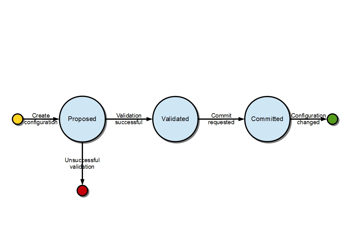
Configuration states
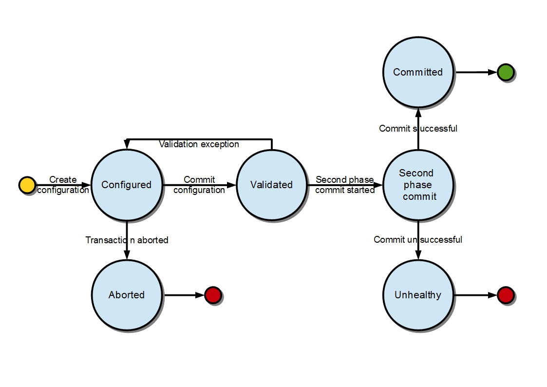
Transaction states
Validation
To secure the consistency and safety of the new configuration and to avoid conflicts, the configuration validation process is necessary. Usually, validation checks the input parameters of a new configuration, and mostly verifies module-specific relationships. The validation procedure results in a decision on whether the proposed configuration is healthy.
Dependency resolver
Since there can be dependencies between modules, a change in a module configuration can affect the state of other modules. Therefore, we need to verify whether dependencies on other modules can be resolved. The Dependency Resolver acts in a manner similar to dependency injectors. Basically, a dependency tree is built.
APIs and SPIs
This section describes configuration system APIs and SPIs.
SPIs
Module org.opendaylight.controller.config.spi. Module is the common interface for all modules: every module must implement it. The module is designated to hold configuration attributes, validate them, and create instances of service based on the attributes. This instance must implement the AutoCloseable interface, owing to resources clean up. If the module was created from an already running instance, it contains an old instance of the module. A module can implement multiple services. If the module depends on other modules, setters need to be annotated with @RequireInterface.
Module creation
The module needs to be configured, set with all required attributes.
The module is then moved to the commit stage for validation. If the validation fails, the module attributes can be reconfigured. Otherwise, a new instance is either created, or an old instance is reconfigured. A module instance is identified by ModuleIdentifier, consisting of the factory name and instance name.
From an existing module instance
- An entirely new instanceModuleFactory can also return default modules, useful for populating registry with already existing configurations. A module factory implementation must have a globally unique name.
APIs
ConfigRegistry |
Represents functionality provided by a configuration transaction (create, destroy module, validate, or abort transaction). |
ConfigTransactionController |
Represents functionality for manipulating with configuration transactions (begin, commit config). |
RuntimeBeanRegistratorAwareConfiBean |
The module implementing this interface will receive RuntimeBeanRegistrator before getInstance is invoked. |
Runtime APIs
RuntimeBean |
Common interface for all runtime beans |
RootRuntimeBeanRegistrator |
Represents functionality for root runtime bean registration, which subsequently allows hierarchical registrations |
HierarchicalRuntimeBeanRegistration |
Represents functionality for runtime bean registration and unreregistration from hierarchy |
JMX APIs
ConfigTransactionControllerMXBean |
Extends ConfigTransactionController, executed by Jolokia clients on configuration transaction. |
ConfigRegistryMXBean |
Represents entry point of configuration management for MXBeans. |
Object names |
Object Name is the pattern used in JMX to locate JMX beans. It consists of domain and key properties (at least one key-value pair). Domain is defined as “org.opendaylight.controller”. The only mandatory property is “type”. |
Use case scenarios
Successful commit scenario
The user creates a transaction calling creteTransaction() method on ConfigRegistry.
ConfigRegisty creates a transaction controller, and registers the transaction as a new bean.
Runtime configurations are copied to the transaction. The user can create modules and set their attributes.
The configuration transaction is to be committed.
The validation process is performed.
After successful validation, the second phase commit begins.
Modules proposed to be destroyed are destroyed, and their service instances are closed.
Runtime beans are set to registrator.
The transaction controller invokes the method getInstance on each module.
The transaction is committed, and resources are either closed or released.
If validation fails, (that is to day, illegal input attributes values or dependency resolver failure), the validationException is thrown and exposed to the user.
The user can decide to reconfigure the transaction and commit again, or abort the current transaction.
On aborted transactions, TransactionController and JMXRegistrator are properly closed.
Unregistration event is sent to ConfigRegistry.
Default module instances
The configuration subsystem provides a way for modules to create default instances. A default instance is an instance of a module, that is created at the module bundle start-up (module becomes visible for configuration subsystem, for example, its bundle is activated in the OSGi environment). By default, no default instances are produced.
The default instance does not differ from instances created later in the module life-cycle. The only difference is that the configuration for the default instance cannot be provided by the configuration subsystem. The module has to acquire the configuration for these instances on its own. It can be acquired from, for example, environment variables. After the creation of a default instance, it acts as a regular instance and fully participates in the configuration subsystem (It can be reconfigured or deleted in following transactions.).